Tutorial 1
DP capability analysis for an offshore wind turbine installation vessel
1 Introduction
This tutorial demonstrates how to use the DP Capability Tool to perform feasibility calculation and capability analyses for an offshore wind turbine installation vessel equipped with:
- 2 azimuth thrusters at the bow
- 3 tunnel thrusters at the stern
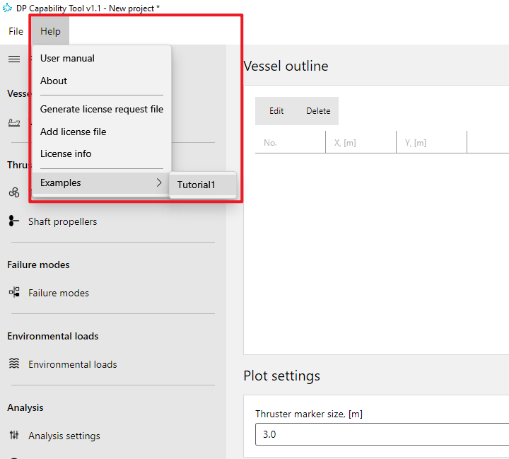
The complete tutorial model is provided within the software and is accessible from the Help menu.
2 Vessel data (Optional)
In a standard DP capability analysis, the first step is to input vessel data, which defines the vessel reference frame and serves as a container for thruster positions.
This step is optional but recommended for clarity and future model extension.
Note: The vessel outline is used for visualization only and does not affect DP calculation results.
Vessel outline coordinates
| X (m) | Y (m) |
|---|---|
| 120.0 | 0.0 |
| 90.0 | 25.0 |
| -120.0 | 25.0 |
| -120.0 | -25.0 |
| 90.0 | -25.0 |
These outline points are linked together into a closed frame, helping users visually check and confirm the thruster locations relative to the vessel’s hull.
3 Thruster configuration
This vessel configuration includes:
Azimuth thrusters (bow)
Capable of generating thrust in any direction from 0° to 360°Tunnel thrusters (stern)
Capable of generating thrust to either port or starboard
There are no shaft propellers in this tutorial case.
3.1 Thrusters
For each azimuth or tunnel thruster, the following parameters must be defined:
- Thruster name
- X coordinate (m)
- Y coordinate (m)
- Propeller diameter (m)
- Maximum power (kW)
- Maximum nominal thrust (kN)
- Default thrust loss factor
Each thruster is positioned relative to the vessel reference coordinate system. When a thrust loss factor curve is not supplied, the default thrust loss factor is applied to calculate the thrust force. It is especially applicable to azimuth thrusters.
3.2 Azimuth thrusters
| Name | X (m) | Y (m) | Diameter (m) | Max power (kW) | Nominal thrust (kN) | Default thrust loss factor |
|---|---|---|---|---|---|---|
| Th1 | -108.6 | -8.2 | 0 | 4,500.00 | 694.428 | 0.9 |
| Th2 | -108.6 | 8.2 | 0 | 4,500.00 | 694.428 | 0.9 |
3.3 Tunnel thrusters
| Name | X (m) | Y (m) | Diameter (m) | Max power (kW) | Nominal thrust (kN) | Default thrust loss factor |
|---|---|---|---|---|---|---|
| Th3 | 102.8 | 0 | 0 | 2,200.00 | 252.36 | 0.9 |
| Th4 | 96.8 | 0 | 0 | 2,200.00 | 252.36 | 0.9 |
| Th5 | 90.2 | 0 | 0 | 2,200.00 | 252.36 | 0.9 |
The thruster position plot displays each azimuth thruster, tunnel thruster, and shaft propeller using a distinct shape and color for each type. When a thruster is selected in the list, it will be highlighted in the plot accordingly.
4 Failure mode definition
Failure modes are organized into failure mode groups, each representing a specific operational scenario, such as:
- Intact condition (all thrusters active)
- Single thruster failure
- Multiple thruster failures
The user must:
- Create a failure mode group with a meaningful name
- Define one or more failure modes within the group
- Specify which thrusters are active or failed in each mode
- Specify azimuth thruster thrust loss factor curves and restricted azimuth sectors
4.1 Azimuth thruster restrictions
For azimuth thrusters, additional constraints can be applied:
- Thrust factor curve over the full 0–360° range
- Multiple forbidden azimuth zones, where thrust is restricted or not allowed
These settings allow realistic modeling of mechanical, structural, or operational limitations.
DNV-ST-0111 and the ABS Guide for Dynamic Positioning Systems provide detailed guidance on how to account for thrust loss factor curves and forbidden zones.
In this tutorial, the thrust loss factor for Th1 is set to 0.9 over the full 360° azimuth range, with a forbidden zone defined between 71° and 109°.
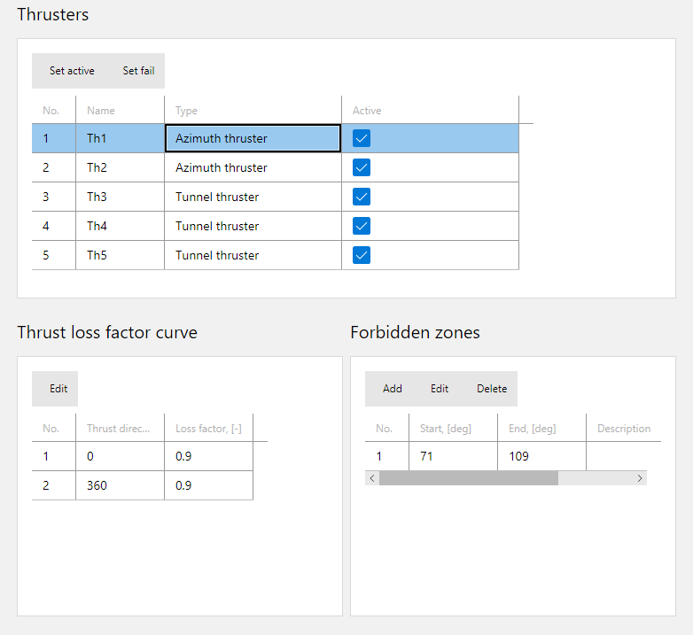
The thrust loss factor for Th2 is identical to that of Th1, while its forbidden zone is defined on the opposite side, ranging from 251° to 289°.
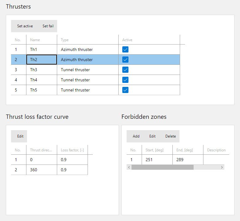
The thrust loss factor curve is presented in the right-side plot, and the forbidden zones are marked on the azimuth thrusters in the thruster position view.
5 Environmental load definition
Environmental loads are defined for both feasibility calculations and capability analysis to assess the resistance capacity of the dynamic positioning system.
Environmental loads are organized into groups, each representing a specific wind speed or wind speed series, which is particularly suitable for capability analysis to evaluate the maximum wind speed or DP capability number that the dynamic positioning system can withstand.
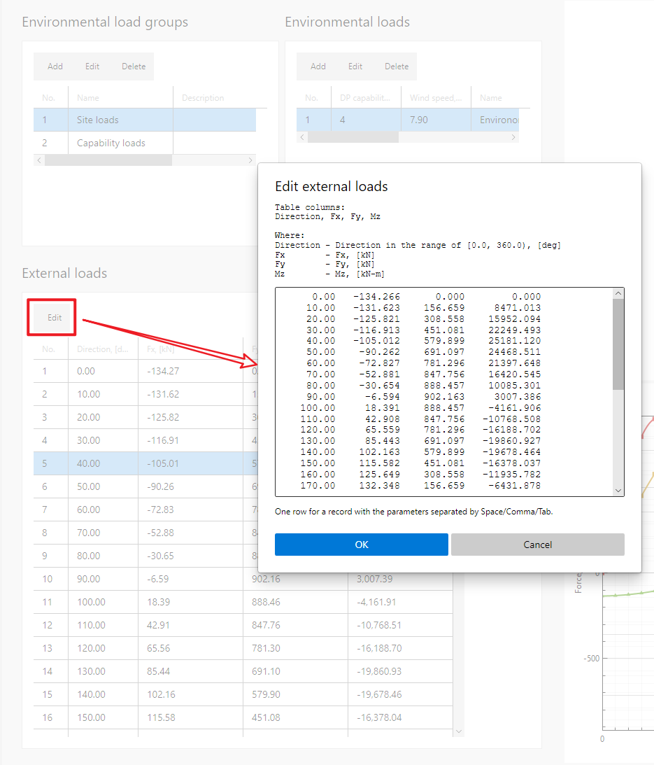
External loads generally arise from wind, current, and waves, and are combined into a resultant load for each direction. These loads should be determined through numerical simulations or physical model tests. Classification guidelines, such as DNV-ST-0111, also provide empirical formulas for simplified evaluation of environmental loads.
Environmental loads can be entered in tabular form, with the first column representing direction and the subsequent three columns defining the Fx, Fy, and Mz components.
In this tutorial, two environmental load groups are used:
5.1 Site loads
The Site loads group contains only one environmental load table, which is used for feasibility calculation and corresponds to a single site-specific environmental condition.
The external load data are provided in the following table.
| Direction (deg) | Fx (kN) | Fy (kN) | Mz (kN-m) |
|---|---|---|---|
| 0.00 | -134.266 | 0.000 | 0.000 |
| 10.00 | -131.623 | 156.659 | 8471.013 |
| 20.00 | -125.821 | 308.558 | 15952.094 |
| 30.00 | -116.913 | 451.081 | 22249.493 |
| 40.00 | -105.012 | 579.899 | 25181.120 |
| 50.00 | -90.262 | 691.097 | 24468.511 |
| 60.00 | -72.827 | 781.296 | 21397.648 |
| 70.00 | -52.881 | 847.756 | 16420.545 |
| 80.00 | -30.654 | 888.457 | 10085.301 |
| 90.00 | -6.594 | 902.163 | 3007.386 |
| 100.00 | 18.391 | 888.457 | -4161.906 |
| 110.00 | 42.908 | 847.756 | -10768.508 |
| 120.00 | 65.559 | 781.296 | -16188.702 |
| 130.00 | 85.443 | 691.097 | -19860.927 |
| 140.00 | 102.163 | 579.899 | -19678.464 |
| 150.00 | 115.582 | 451.081 | -16378.037 |
| 160.00 | 125.649 | 308.558 | -11935.782 |
| 170.00 | 132.348 | 156.659 | -6431.878 |
| 180.00 | 135.698 | 0.000 | 0.000 |
| 190.00 | 132.348 | -156.659 | 6431.878 |
| 200.00 | 125.649 | -308.558 | 11935.782 |
| 210.00 | 115.582 | -451.081 | 16378.037 |
| 220.00 | 102.163 | -579.899 | 19678.464 |
| 230.00 | 85.443 | -691.097 | 19860.927 |
| 240.00 | 65.559 | -781.296 | 16188.702 |
| 250.00 | 42.908 | -847.756 | 10768.508 |
| 260.00 | 18.391 | -888.457 | 4161.906 |
| 270.00 | -6.594 | -902.163 | -3007.386 |
| 280.00 | -30.654 | -888.457 | -10085.301 |
| 290.00 | -52.881 | -847.756 | -16420.545 |
| 300.00 | -72.827 | -781.296 | -21397.648 |
| 310.00 | -90.262 | -691.097 | -24468.511 |
| 320.00 | -105.012 | -579.899 | -25181.120 |
| 330.00 | -116.913 | -451.081 | -22249.493 |
| 340.00 | -125.821 | -308.558 | -15952.094 |
| 350.00 | -131.623 | -156.659 | -8471.013 |
5.2 Capability loads
The Capability loads group consists of 11 environmental load tables corresponding to different Beaufort scale levels, each associated with a specific wind speed and DP capability number. The wind speed, significant wave height, peak wave period, and current speed for each Beaufort level are taken from DNV-ST-0111 to evaluate wind-, wave-, and current-induced loads.
This group is used to determine the maximum wind speed or DP capability number that the DP system can withstand.
When you select an environmental load table, the wind rose and component load curves appear in the plot views on the right.
The external load data are provided in the following tables.
5.2.1 DP capability number 1
| Direction (deg) | Fx (kN) | Fy (kN) | Mz (kN-m) |
|---|---|---|---|
| 0.00 | -4.956 | 0.000 | 0.000 |
| 10.00 | -4.877 | 11.102 | 690.490 |
| 20.00 | -4.655 | 21.867 | 1336.938 |
| 30.00 | -4.296 | 31.967 | 1920.758 |
| 40.00 | -3.809 | 41.096 | 2198.655 |
| 50.00 | -3.209 | 48.977 | 2135.218 |
| 60.00 | -2.512 | 55.369 | 1865.556 |
| 70.00 | -1.736 | 60.079 | 1429.262 |
| 80.00 | -0.904 | 62.963 | 874.330 |
| 90.00 | -0.039 | 63.935 | 254.648 |
| 100.00 | 0.831 | 62.963 | -372.772 |
| 110.00 | 1.677 | 60.079 | -950.680 |
| 120.00 | 2.469 | 55.369 | -1424.493 |
| 130.00 | 3.181 | 48.977 | -1745.075 |
| 140.00 | 3.793 | 41.096 | -1689.460 |
| 150.00 | 4.288 | 31.967 | -1347.880 |
| 160.00 | 4.654 | 21.867 | -945.066 |
| 170.00 | 4.882 | 11.102 | -491.532 |
| 180.00 | 4.965 | 0.000 | 0.000 |
| 190.00 | 4.882 | -11.102 | 491.532 |
| 200.00 | 4.654 | -21.867 | 945.066 |
| 210.00 | 4.288 | -31.967 | 1347.880 |
| 220.00 | 3.793 | -41.096 | 1689.460 |
| 230.00 | 3.181 | -48.977 | 1745.075 |
| 240.00 | 2.469 | -55.369 | 1424.493 |
| 250.00 | 1.677 | -60.079 | 950.680 |
| 260.00 | 0.831 | -62.963 | 372.772 |
| 270.00 | -0.039 | -63.935 | -254.648 |
| 280.00 | -0.904 | -62.963 | -874.330 |
| 290.00 | -1.736 | -60.079 | -1429.262 |
| 300.00 | -2.512 | -55.369 | -1865.556 |
| 310.00 | -3.209 | -48.977 | -2135.218 |
| 320.00 | -3.809 | -41.096 | -2198.655 |
| 330.00 | -4.296 | -31.967 | -1920.758 |
| 340.00 | -4.655 | -21.867 | -1336.938 |
| 350.00 | -4.877 | -11.102 | -690.490 |
5.2.2 DP capability number 2
| Direction (deg) | Fx (kN) | Fy (kN) | Mz (kN-m) |
|---|---|---|---|
| 0.00 | -25.769 | 0.000 | 0.000 |
| 10.00 | -25.320 | 48.273 | 2903.122 |
| 20.00 | -24.182 | 95.080 | 5592.408 |
| 30.00 | -22.377 | 138.997 | 7991.899 |
| 40.00 | -19.944 | 178.692 | 9128.956 |
| 50.00 | -16.939 | 212.956 | 8864.557 |
| 60.00 | -13.424 | 240.750 | 7743.636 |
| 70.00 | -9.472 | 261.230 | 5930.685 |
| 80.00 | -5.170 | 273.771 | 3625.103 |
| 90.00 | -0.624 | 277.995 | 1050.749 |
| 100.00 | 4.009 | 273.771 | -1555.531 |
| 110.00 | 8.528 | 261.230 | -3955.922 |
| 120.00 | 12.735 | 240.750 | -5923.684 |
| 130.00 | 16.482 | 212.956 | -7254.716 |
| 140.00 | 19.675 | 178.692 | -7050.835 |
| 150.00 | 22.251 | 138.997 | -5668.230 |
| 160.00 | 24.166 | 95.080 | -4002.924 |
| 170.00 | 25.389 | 48.273 | -2096.120 |
| 180.00 | 25.905 | 0.000 | 0.000 |
| 190.00 | 25.389 | -48.273 | 2096.120 |
| 200.00 | 24.166 | -95.080 | 4002.924 |
| 210.00 | 22.251 | -138.997 | 5668.230 |
| 220.00 | 19.675 | -178.692 | 7050.835 |
| 230.00 | 16.482 | -212.956 | 7254.716 |
| 240.00 | 12.735 | -240.750 | 5923.684 |
| 250.00 | 8.528 | -261.230 | 3955.922 |
| 260.00 | 4.009 | -273.771 | 1555.531 |
| 270.00 | -0.624 | -277.995 | -1050.749 |
| 280.00 | -5.170 | -273.771 | -3625.103 |
| 290.00 | -9.472 | -261.230 | -5930.685 |
| 300.00 | -13.424 | -240.750 | -7743.636 |
| 310.00 | -16.939 | -212.956 | -8864.557 |
| 320.00 | -19.944 | -178.692 | -9128.956 |
| 330.00 | -22.377 | -138.997 | -7991.899 |
| 340.00 | -24.182 | -95.080 | -5592.408 |
| 350.00 | -25.320 | -48.273 | -2903.122 |
5.2.3 DP capability number 3
| Direction (deg) | Fx (kN) | Fy (kN) | Mz (kN-m) |
|---|---|---|---|
| 0.00 | -68.192 | 0.000 | 0.000 |
| 10.00 | -66.928 | 115.800 | 6729.700 |
| 20.00 | -63.948 | 228.082 | 12922.488 |
| 30.00 | -59.297 | 333.434 | 18405.429 |
| 40.00 | -53.056 | 428.655 | 20991.250 |
| 50.00 | -45.332 | 510.851 | 20371.374 |
| 60.00 | -36.252 | 577.525 | 17778.888 |
| 70.00 | -25.959 | 626.651 | 13593.258 |
| 80.00 | -14.621 | 656.737 | 8274.349 |
| 90.00 | -2.497 | 666.868 | 2338.346 |
| 100.00 | 9.977 | 656.737 | -3668.707 |
| 110.00 | 22.182 | 626.651 | -9198.605 |
| 120.00 | 33.500 | 577.525 | -13728.754 |
| 130.00 | 43.507 | 510.851 | -16788.820 |
| 140.00 | 51.977 | 428.655 | -16348.696 |
| 150.00 | 58.793 | 333.434 | -13203.013 |
| 160.00 | 63.883 | 228.082 | -9363.826 |
| 170.00 | 67.203 | 115.800 | -4922.920 |
| 180.00 | 68.735 | 0.000 | 0.000 |
| 190.00 | 67.203 | -115.800 | 4922.920 |
| 200.00 | 63.883 | -228.082 | 9363.826 |
| 210.00 | 58.793 | -333.434 | 13203.013 |
| 220.00 | 51.977 | -428.655 | 16348.696 |
| 230.00 | 43.507 | -510.851 | 16788.820 |
| 240.00 | 33.500 | -577.525 | 13728.754 |
| 250.00 | 22.182 | -626.651 | 9198.605 |
| 260.00 | 9.977 | -656.737 | 3668.707 |
| 270.00 | -2.497 | -666.868 | -2338.346 |
| 280.00 | -14.621 | -656.737 | -8274.349 |
| 290.00 | -25.959 | -626.651 | -13593.258 |
| 300.00 | -36.252 | -577.525 | -17778.888 |
| 310.00 | -45.332 | -510.851 | -20371.374 |
| 320.00 | -53.056 | -428.655 | -20991.250 |
| 330.00 | -59.297 | -333.434 | -18405.429 |
| 340.00 | -63.948 | -228.082 | -12922.488 |
| 350.00 | -66.928 | -115.800 | -6729.700 |
5.2.4 DP capability number 4
| Direction (deg) | Fx (kN) | Fy (kN) | Mz (kN-m) |
|---|---|---|---|
| 0.00 | -134.266 | 0.000 | 0.000 |
| 10.00 | -131.623 | 156.659 | 8471.013 |
| 20.00 | -125.821 | 308.558 | 15952.094 |
| 30.00 | -116.913 | 451.081 | 22249.493 |
| 40.00 | -105.012 | 579.899 | 25181.120 |
| 50.00 | -90.262 | 691.097 | 24468.511 |
| 60.00 | -72.827 | 781.296 | 21397.648 |
| 70.00 | -52.881 | 847.756 | 16420.545 |
| 80.00 | -30.654 | 888.457 | 10085.301 |
| 90.00 | -6.594 | 902.163 | 3007.386 |
| 100.00 | 18.391 | 888.457 | -4161.906 |
| 110.00 | 42.908 | 847.756 | -10768.508 |
| 120.00 | 65.559 | 781.296 | -16188.702 |
| 130.00 | 85.443 | 691.097 | -19860.927 |
| 140.00 | 102.163 | 579.899 | -19678.464 |
| 150.00 | 115.582 | 451.081 | -16378.037 |
| 160.00 | 125.649 | 308.558 | -11935.782 |
| 170.00 | 132.348 | 156.659 | -6431.878 |
| 180.00 | 135.698 | 0.000 | 0.000 |
| 190.00 | 132.348 | -156.659 | 6431.878 |
| 200.00 | 125.649 | -308.558 | 11935.782 |
| 210.00 | 115.582 | -451.081 | 16378.037 |
| 220.00 | 102.163 | -579.899 | 19678.464 |
| 230.00 | 85.443 | -691.097 | 19860.927 |
| 240.00 | 65.559 | -781.296 | 16188.702 |
| 250.00 | 42.908 | -847.756 | 10768.508 |
| 260.00 | 18.391 | -888.457 | 4161.906 |
| 270.00 | -6.594 | -902.163 | -3007.386 |
| 280.00 | -30.654 | -888.457 | -10085.301 |
| 290.00 | -52.881 | -847.756 | -16420.545 |
| 300.00 | -72.827 | -781.296 | -21397.648 |
| 310.00 | -90.262 | -691.097 | -24468.511 |
| 320.00 | -105.012 | -579.899 | -25181.120 |
| 330.00 | -116.913 | -451.081 | -22249.493 |
| 340.00 | -125.821 | -308.558 | -15952.094 |
| 350.00 | -131.623 | -156.659 | -8471.013 |
5.2.5 DP capability number 5
| Direction (deg) | Fx (kN) | Fy (kN) | Mz (kN-m) |
|---|---|---|---|
| 0.00 | -261.302 | 0.000 | 0.000 |
| 10.00 | -255.760 | 240.402 | 11393.297 |
| 20.00 | -244.636 | 473.499 | 21010.477 |
| 30.00 | -227.954 | 692.210 | 28624.834 |
| 40.00 | -205.801 | 889.888 | 32066.431 |
| 50.00 | -178.289 | 1060.527 | 31112.110 |
| 60.00 | -145.510 | 1198.943 | 27142.482 |
| 70.00 | -107.531 | 1300.929 | 20737.985 |
| 80.00 | -64.526 | 1363.387 | 12601.961 |
| 90.00 | -17.206 | 1384.420 | 3523.830 |
| 100.00 | 32.527 | 1363.387 | -5661.370 |
| 110.00 | 81.507 | 1300.929 | -14115.350 |
| 120.00 | 126.544 | 1198.943 | -21039.029 |
| 130.00 | 165.714 | 1060.527 | -25713.288 |
| 140.00 | 198.368 | 889.888 | -25899.848 |
| 150.00 | 224.479 | 692.210 | -22236.934 |
| 160.00 | 244.187 | 473.499 | -16640.896 |
| 170.00 | 257.652 | 240.402 | -9174.803 |
| 180.00 | 265.039 | 0.000 | 0.000 |
| 190.00 | 257.652 | -240.402 | 9174.803 |
| 200.00 | 244.187 | -473.499 | 16640.896 |
| 210.00 | 224.479 | -692.210 | 22236.934 |
| 220.00 | 198.368 | -889.888 | 25899.848 |
| 230.00 | 165.714 | -1060.527 | 25713.288 |
| 240.00 | 126.544 | -1198.943 | 21039.029 |
| 250.00 | 81.507 | -1300.929 | 14115.350 |
| 260.00 | 32.527 | -1363.387 | 5661.370 |
| 270.00 | -17.206 | -1384.420 | -3523.830 |
| 280.00 | -64.526 | -1363.387 | -12601.961 |
| 290.00 | -107.531 | -1300.929 | -20737.985 |
| 300.00 | -145.510 | -1198.943 | -27142.482 |
| 310.00 | -178.289 | -1060.527 | -31112.110 |
| 320.00 | -205.801 | -889.888 | -32066.431 |
| 330.00 | -227.954 | -692.210 | -28624.834 |
| 340.00 | -244.636 | -473.499 | -21010.477 |
| 350.00 | -255.760 | -240.402 | -11393.297 |
5.2.6 DP capability number 6
| Direction (deg) | Fx (kN) | Fy (kN) | Mz (kN-m) |
|---|---|---|---|
| 0.00 | -464.248 | 0.000 | 0.000 |
| 10.00 | -453.921 | 385.173 | 15878.418 |
| 20.00 | -434.361 | 758.643 | 28746.335 |
| 30.00 | -405.508 | 1109.062 | 38328.577 |
| 40.00 | -367.365 | 1425.782 | 42477.558 |
| 50.00 | -319.922 | 1699.181 | 41060.107 |
| 60.00 | -263.070 | 1920.951 | 35608.347 |
| 70.00 | -196.603 | 2084.354 | 26906.963 |
| 80.00 | -120.502 | 2184.425 | 15905.243 |
| 90.00 | -35.834 | 2218.124 | 3667.421 |
| 100.00 | 53.858 | 2184.425 | -8681.833 |
| 110.00 | 142.406 | 2084.354 | -20014.466 |
| 120.00 | 223.571 | 1920.951 | -29256.187 |
| 130.00 | 293.732 | 1699.181 | -35441.292 |
| 140.00 | 351.884 | 1425.782 | -36126.378 |
| 150.00 | 398.269 | 1109.062 | -31797.086 |
| 160.00 | 433.426 | 758.643 | -24278.532 |
| 170.00 | 457.861 | 385.173 | -13610.055 |
| 180.00 | 472.032 | 0.000 | 0.000 |
| 190.00 | 457.861 | -385.173 | 13610.055 |
| 200.00 | 433.426 | -758.643 | 24278.532 |
| 210.00 | 398.269 | -1109.062 | 31797.086 |
| 220.00 | 351.884 | -1425.782 | 36126.378 |
| 230.00 | 293.732 | -1699.181 | 35441.292 |
| 240.00 | 223.571 | -1920.951 | 29256.187 |
| 250.00 | 142.406 | -2084.354 | 20014.466 |
| 260.00 | 53.858 | -2184.425 | 8681.833 |
| 270.00 | -35.834 | -2218.124 | -3667.421 |
| 280.00 | -120.502 | -2184.425 | -15905.243 |
| 290.00 | -196.603 | -2084.354 | -26906.963 |
| 300.00 | -263.070 | -1920.951 | -35608.347 |
| 310.00 | -319.922 | -1699.181 | -41060.107 |
| 320.00 | -367.365 | -1425.782 | -42477.558 |
| 330.00 | -405.508 | -1109.062 | -38328.577 |
| 340.00 | -434.361 | -758.643 | -28746.335 |
| 350.00 | -453.921 | -385.173 | -15878.418 |
5.2.7 DP capability number 7
| Direction (deg) | Fx (kN) | Fy (kN) | Mz (kN-m) |
|---|---|---|---|
| 0.00 | -744.060 | 0.000 | 0.000 |
| 10.00 | -727.077 | 594.236 | 22090.086 |
| 20.00 | -695.910 | 1170.416 | 39437.695 |
| 30.00 | -650.370 | 1711.034 | 51702.237 |
| 40.00 | -590.328 | 2199.663 | 56770.066 |
| 50.00 | -515.578 | 2621.457 | 54636.767 |
| 60.00 | -425.703 | 2963.598 | 47049.363 |
| 70.00 | -320.081 | 3215.693 | 35081.182 |
| 80.00 | -198.384 | 3370.080 | 20028.335 |
| 90.00 | -62.152 | 3422.069 | 3341.994 |
| 100.00 | 82.796 | 3370.080 | -13445.891 |
| 110.00 | 226.080 | 3215.693 | -28800.287 |
| 120.00 | 357.196 | 2963.598 | -41260.858 |
| 130.00 | 470.154 | 2621.457 | -49516.535 |
| 140.00 | 563.477 | 2199.663 | -50837.247 |
| 150.00 | 637.817 | 1711.034 | -45496.173 |
| 160.00 | 694.288 | 1170.416 | -35192.497 |
| 170.00 | 733.910 | 594.236 | -19934.743 |
| 180.00 | 757.560 | 0.000 | 0.000 |
| 190.00 | 733.910 | -594.236 | 19934.743 |
| 200.00 | 694.288 | -1170.416 | 35192.497 |
| 210.00 | 637.817 | -1711.034 | 45496.173 |
| 220.00 | 563.477 | -2199.663 | 50837.247 |
| 230.00 | 470.154 | -2621.457 | 49516.535 |
| 240.00 | 357.196 | -2963.598 | 41260.858 |
| 250.00 | 226.080 | -3215.693 | 28800.287 |
| 260.00 | 82.796 | -3370.080 | 13445.891 |
| 270.00 | -62.152 | -3422.069 | -3341.994 |
| 280.00 | -198.384 | -3370.080 | -20028.335 |
| 290.00 | -320.081 | -3215.693 | -35081.182 |
| 300.00 | -425.703 | -2963.598 | -47049.363 |
| 310.00 | -515.578 | -2621.457 | -54636.767 |
| 320.00 | -590.328 | -2199.663 | -56770.066 |
| 330.00 | -650.370 | -1711.034 | -51702.237 |
| 340.00 | -695.910 | -1170.416 | -39437.695 |
| 350.00 | -727.077 | -594.236 | -22090.086 |
5.2.8 DP capability number 8
| Direction (deg) | Fx (kN) | Fy (kN) | Mz (kN-m) |
|---|---|---|---|
| 0.00 | -1124.634 | 0.000 | 0.000 |
| 10.00 | -1098.545 | 901.735 | 31128.605 |
| 20.00 | -1051.614 | 1776.071 | 54908.885 |
| 30.00 | -983.469 | 2596.442 | 70911.595 |
| 40.00 | -893.780 | 3337.922 | 77083.888 |
| 50.00 | -782.053 | 3977.980 | 73624.465 |
| 60.00 | -647.422 | 4497.170 | 62612.411 |
| 70.00 | -488.661 | 4879.715 | 45563.117 |
| 80.00 | -304.983 | 5113.993 | 24301.045 |
| 90.00 | -98.549 | 5192.885 | 864.600 |
| 100.00 | 121.704 | 5113.993 | -22598.116 |
| 110.00 | 339.611 | 4879.715 | -43938.201 |
| 120.00 | 538.796 | 4497.170 | -61114.881 |
| 130.00 | 710.028 | 3977.980 | -72299.821 |
| 140.00 | 851.205 | 3337.922 | -74335.946 |
| 150.00 | 963.563 | 2596.442 | -67182.926 |
| 160.00 | 1049.042 | 1776.071 | -52358.325 |
| 170.00 | 1109.379 | 901.735 | -29833.651 |
| 180.00 | 1146.040 | 0.000 | 0.000 |
| 190.00 | 1109.379 | -901.735 | 29833.651 |
| 200.00 | 1049.042 | -1776.071 | 52358.325 |
| 210.00 | 963.563 | -2596.442 | 67182.926 |
| 220.00 | 851.205 | -3337.922 | 74335.946 |
| 230.00 | 710.028 | -3977.980 | 72299.821 |
| 240.00 | 538.796 | -4497.170 | 61114.881 |
| 250.00 | 339.611 | -4879.715 | 43938.201 |
| 260.00 | 121.704 | -5113.993 | 22598.116 |
| 270.00 | -98.549 | -5192.885 | -864.600 |
| 280.00 | -304.983 | -5113.993 | -24301.045 |
| 290.00 | -488.661 | -4879.715 | -45563.117 |
| 300.00 | -647.422 | -4497.170 | -62612.411 |
| 310.00 | -782.053 | -3977.980 | -73624.465 |
| 320.00 | -893.780 | -3337.922 | -77083.888 |
| 330.00 | -983.469 | -2596.442 | -70911.595 |
| 340.00 | -1051.614 | -1776.071 | -54908.885 |
| 350.00 | -1098.545 | -901.735 | -31128.605 |
5.2.9 DP capability number 9
| Direction (deg) | Fx (kN) | Fy (kN) | Mz (kN-m) |
|---|---|---|---|
| 0.00 | -1643.573 | 0.000 | 0.000 |
| 10.00 | -1604.671 | 1323.829 | 42947.809 |
| 20.00 | -1536.413 | 2607.435 | 75062.596 |
| 30.00 | -1438.088 | 3811.815 | 95805.061 |
| 40.00 | -1308.969 | 4900.374 | 103212.148 |
| 50.00 | -1148.000 | 5840.039 | 97762.357 |
| 60.00 | -953.477 | 6602.257 | 81986.442 |
| 70.00 | -723.084 | 7163.868 | 57997.720 |
| 80.00 | -455.140 | 7507.809 | 28332.900 |
| 90.00 | -152.494 | 7623.629 | -4179.924 |
| 100.00 | 171.536 | 7507.809 | -36565.743 |
| 110.00 | 492.446 | 7163.868 | -65853.408 |
| 120.00 | 785.390 | 6602.257 | -89226.283 |
| 130.00 | 1036.549 | 5840.039 | -104166.372 |
| 140.00 | 1243.089 | 4900.374 | -106949.320 |
| 150.00 | 1407.286 | 3811.815 | -97120.916 |
| 160.00 | 1532.433 | 2607.435 | -75962.693 |
| 170.00 | 1621.436 | 1323.829 | -43404.800 |
| 180.00 | 1676.696 | 0.000 | 0.000 |
| 190.00 | 1621.436 | -1323.829 | 43404.800 |
| 200.00 | 1532.433 | -2607.435 | 75962.693 |
| 210.00 | 1407.286 | -3811.815 | 97120.916 |
| 220.00 | 1243.089 | -4900.374 | 106949.320 |
| 230.00 | 1036.549 | -5840.039 | 104166.372 |
| 240.00 | 785.390 | -6602.257 | 89226.283 |
| 250.00 | 492.446 | -7163.868 | 65853.408 |
| 260.00 | 171.536 | -7507.809 | 36565.743 |
| 270.00 | -152.494 | -7623.629 | 4179.924 |
| 280.00 | -455.140 | -7507.809 | -28332.900 |
| 290.00 | -723.084 | -7163.868 | -57997.720 |
| 300.00 | -953.477 | -6602.257 | -81986.442 |
| 310.00 | -1148.000 | -5840.039 | -97762.357 |
| 320.00 | -1308.969 | -4900.374 | -103212.148 |
| 330.00 | -1438.088 | -3811.815 | -95805.061 |
| 340.00 | -1536.413 | -2607.435 | -75062.596 |
| 350.00 | -1604.671 | -1323.829 | -42947.809 |
5.2.10 DP capability number 10
| Direction (deg) | Fx (kN) | Fy (kN) | Mz (kN-m) |
|---|---|---|---|
| 0.00 | -2238.785 | 0.000 | 0.000 |
| 10.00 | -2185.605 | 1821.944 | 59230.178 |
| 20.00 | -2092.708 | 3588.528 | 102696.564 |
| 30.00 | -1959.084 | 5246.078 | 129718.166 |
| 40.00 | -1783.686 | 6744.227 | 138472.969 |
| 50.00 | -1564.988 | 8037.457 | 129848.888 |
| 60.00 | -1300.566 | 9086.473 | 107028.331 |
| 70.00 | -987.136 | 9859.401 | 72981.846 |
| 80.00 | -622.277 | 10332.756 | 31263.357 |
| 90.00 | -209.794 | 10492.155 | -14174.369 |
| 100.00 | 232.107 | 10332.756 | -59181.413 |
| 110.00 | 669.834 | 9859.401 | -99620.945 |
| 120.00 | 1069.319 | 9086.473 | -131579.058 |
| 130.00 | 1411.659 | 8037.457 | -151565.281 |
| 140.00 | 1693.050 | 6744.227 | -155058.753 |
| 150.00 | 1916.708 | 5246.078 | -141028.465 |
| 160.00 | 2087.233 | 3588.528 | -110433.264 |
| 170.00 | 2208.670 | 1821.944 | -63158.204 |
| 180.00 | 2284.355 | 0.000 | 0.000 |
| 190.00 | 2208.670 | -1821.944 | 63158.204 |
| 200.00 | 2087.233 | -3588.528 | 110433.264 |
| 210.00 | 1916.708 | -5246.078 | 141028.465 |
| 220.00 | 1693.050 | -6744.227 | 155058.753 |
| 230.00 | 1411.659 | -8037.457 | 151565.281 |
| 240.00 | 1069.319 | -9086.473 | 131579.058 |
| 250.00 | 669.834 | -9859.401 | 99620.945 |
| 260.00 | 232.107 | -10332.756 | 59181.413 |
| 270.00 | -209.794 | -10492.155 | 14174.369 |
| 280.00 | -622.277 | -10332.756 | -31263.357 |
| 290.00 | -987.136 | -9859.401 | -72981.846 |
| 300.00 | -1300.566 | -9086.473 | -107028.331 |
| 310.00 | -1564.988 | -8037.457 | -129848.888 |
| 320.00 | -1783.686 | -6744.227 | -138472.969 |
| 330.00 | -1959.084 | -5246.078 | -129718.166 |
| 340.00 | -2092.708 | -3588.528 | -102696.564 |
| 350.00 | -2185.605 | -1821.944 | -59230.178 |
5.2.11 DP capability number 11
| Direction (deg) | Fx (kN) | Fy (kN) | Mz (kN-m) |
|---|---|---|---|
| 0.00 | -3134.743 | 0.000 | 0.000 |
| 10.00 | -3058.769 | 2593.079 | 81356.772 |
| 20.00 | -2929.333 | 5107.370 | 140034.533 |
| 30.00 | -2744.702 | 7466.475 | 175176.097 |
| 40.00 | -2502.930 | 9598.715 | 185179.720 |
| 50.00 | -2201.223 | 11439.303 | 171529.173 |
| 60.00 | -1835.338 | 12932.314 | 138340.945 |
| 70.00 | -1399.648 | 14032.383 | 89805.760 |
| 80.00 | -889.726 | 14706.085 | 30919.244 |
| 90.00 | -310.298 | 14932.950 | -32776.846 |
| 100.00 | 312.642 | 14706.085 | -95477.029 |
| 110.00 | 930.340 | 14032.383 | -151406.081 |
| 120.00 | 1493.310 | 12932.314 | -195112.108 |
| 130.00 | 1974.441 | 11439.303 | -221746.215 |
| 140.00 | 2368.874 | 9598.715 | -225680.388 |
| 150.00 | 2682.026 | 7466.475 | -205088.874 |
| 160.00 | 2921.236 | 5107.370 | -160496.078 |
| 170.00 | 3092.883 | 2593.079 | -91745.370 |
| 180.00 | 3202.143 | 0.000 | 0.000 |
| 190.00 | 3092.883 | -2593.079 | 91745.370 |
| 200.00 | 2921.236 | -5107.370 | 160496.078 |
| 210.00 | 2682.026 | -7466.475 | 205088.874 |
| 220.00 | 2368.874 | -9598.715 | 225680.388 |
| 230.00 | 1974.441 | -11439.303 | 221746.215 |
| 240.00 | 1493.310 | -12932.314 | 195112.108 |
| 250.00 | 930.340 | -14032.383 | 151406.081 |
| 260.00 | 312.642 | -14706.085 | 95477.029 |
| 270.00 | -310.298 | -14932.950 | 32776.846 |
| 280.00 | -889.726 | -14706.085 | -30919.244 |
| 290.00 | -1399.648 | -14032.383 | -89805.760 |
| 300.00 | -1835.338 | -12932.314 | -138340.945 |
| 310.00 | -2201.223 | -11439.303 | -171529.173 |
| 320.00 | -2502.930 | -9598.715 | -185179.720 |
| 330.00 | -2744.702 | -7466.475 | -175176.097 |
| 340.00 | -2929.333 | -5107.370 | -140034.533 |
| 350.00 | -3058.769 | -2593.079 | -81356.772 |
6 Analysis settings
In the Analysis settings panel, users can define Skipped zones, which represent heading sectors that are not of operational interest. These sectors are excluded from the analysis to reduce computational effort and focus the calculations on applicable headings. When skipped zones are defined, the rose plots are updated accordingly.
7 Feasibility calcuation
A feasibility calculation evaluates whether a dynamic positioning (DP) system can maintain position under a given, fixed environmental condition for specified headings and failure modes.
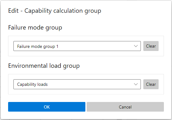
7.1 Defining an analysis case
A feasibility calculation or capability analysis is configured by selecting:
- One Failure mode group
- One Environmental load group
Each selected pair forms a unique DP analysis case, which is evaluated independently.
In this tutorial, two calculation groups are configured. The first calculation group combines Failure mode group 1 with Site loads.

The second calculation group combines Failure mode group 1 with Capability loads.

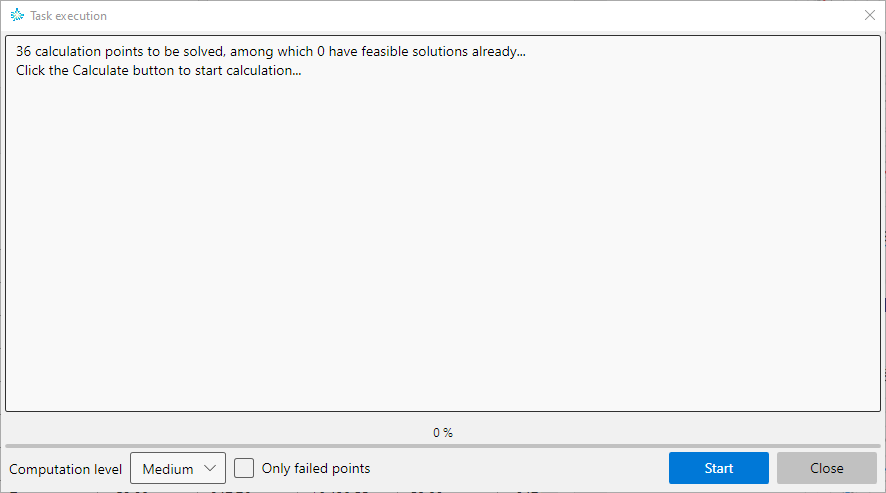
7.2 Running Calculations
The DP Capability Tool allows feasibility calculations to be executed either as a single case or in batch mode.
For each analysis case, the DP Capability Tool formulates an optimization problem at every heading or environmental direction (calculation point). The solver determines an optimal thrust allocation using the available azimuth thrusters, tunnel thrusters, and shaft propellers.
Repeating the calculation increases the likelihood of identifying a feasible or improved solution. The tool also provides an option to rerun calculations only for previously failed calculation points, improving efficiency while enhancing overall solution robustness.
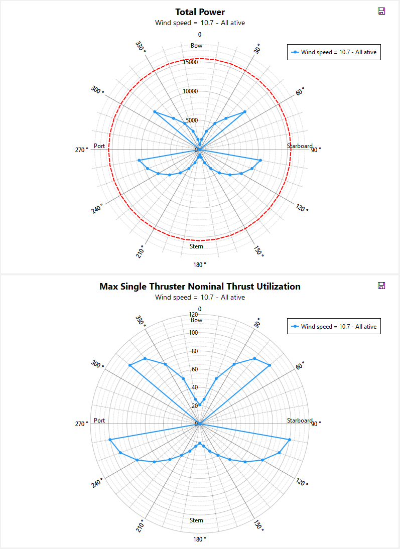
In the first calculation group, a single calculation is performed to determine a feasible solution for each environmental direction. The resulting feasibility calculation is displayed as rose plots on the right side of the interface, while detailed numerical results are available in tabular form.
In the second calcuation group, as the wind speed increases, no feasible solution can be found for some certain direction and the rose plots of total power and maximum single thruster nominal thrust utilization become discontinuous.
In the second calculation group, as the wind speed increases, feasible solutions can no longer be found for certain directions. As a result, the rose plots of total power and maximum single-thruster nominal thrust utilization become discontinuous.
8 Capability analysis
A capability analysis assesses the maximum environmental severity (typically increasing wind speed) that the DP system can withstand before no feasible solution exists. Feasibility calculations are commonly used for site-specific operational assessments, while capability analyses are mainly applied for DP performance evaluation and verification.
| Aspect | Feasibility calculation | Capability analysis |
|---|---|---|
| Environmental loads | Single fixed condition | Multiple increasing conditions |
| Key question | Can the DP system hold position? | How much environment can it withstand? |
| Typical output | Feasible / not feasible | Maximum wind speed or DP capability number |
| Typical application | Operational planning, site assessment | Design evaluation, DP performance assessment |
In this tutorial, one calculation group is configured by combining Failure mode group 1 with Capability loads.
The results of the capability analysis are presented on the right side of the interface as rose plots showing the maximum wind speed and DP capability number, with detailed numerical results provided in tabular form.
9 Reporting
Since all calculations in this tutorial are pre-computed, the user can directly use the reporting function.
Key features include:
- User-selectable report content
- Automatic formatting
- One-click generation of a complete DP work report
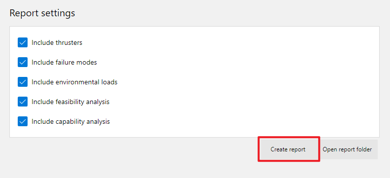
A Word report can be automatically generated, containing all input data, calculation tables, and result figures for documentation and review purposes.